 Chamfer Point to Point Command
- Step-By-Step
- Undo
- Tips and Tricks
- Related Tools
1. Before using this tool:
1a: Go to an isometric view that shows the length, width and depth of the desired chamfer operation.
2. Preselect a material to enable the Materials contextual page and click the Chamfer Edge icon found in the Operations section. Skip step 3.
Alternative: Invoke Chamfer Point to Point using the Find Tool by searching the command name and clicking the Chamfer Point to Point icon, which is pictured above. Proceed to step 3.
Learn more about alternative methods for launching commands.
3. Skip this step if you already selected a material in step 2.
3a: Chamfer Point to Point gives you Select One Item mouse bindings and prompts you to "Select material". This prompting also occurs if a member, bolt or weld (rather than material) was selected.
|
|
|
Select One Item bindings |
4. Locate - Pan - Cancel mouse bindings become active. The status line prompts, "Locate chamfer begin". The point locator On Polygon Line becomes active.
|
|
|
bindings |
|
|
Locate chamfer length |
4a: Left-click (Locate) one end of the length you want to chamfer (pt1 in the example above). Then left-click (Locate) the opposite end of that length (
in the example above).
5. The first point that you located in step 4a (pt1 in the examples) is used as the base point for designating the width direction. The status line prompts, "Locate width direction" On Polygon Line continues to be the active point locator.
|
|
|
bindings |
|
|
Locate width direction |
5a: Left-click (Locate) a point that designates a direction perpendicular to the length you designated in step 4a. This sets the direction of the Chamfer width that you will enter in step 7.
6. The status line prompts, "Locate depth direction". Locate - Pan - Cancel mouse bindings remain active. On Polygon Line continues to be the active point locator.
|
|
|
bindings |
|
|
Locate depth direction |
6a: Left-click (Locate) a point that designates a direction away from the length you located in step 4a. The located point identifies the side of the camber length that the Chamfer depth entered in step 7 will be on.
7. The Chamfer Point to Point window opens. Enter a Chamfer depth and either a Chamfer width or a
Chamfer angle.
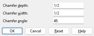
Chamfer depth: The distance (in the primary dimension Units or other units) from the length that you designated in step 4a to the point where you want the chamfer to end. Chamfer depth is perpendicular to the Chamfer width and is on the side of the chamfer length that is the depth direction designated in step 6a.
Chamfer width: The distance (in the primary dimension Units or other units) from the edge located in step 4a to the new edge on that same surface that results after the chamfering takes place. The Chamfer width is parallel with the width direction designated in step 5a. This distance is calculated automatically when you enter a Chamfer depth and a Chamfer angle.
Chamfer angle: The number (of degrees) that defines the angle of the chamfering. This angle is calculated automatically when you enter a Chamfer depth and a Chamfer width. The value you enter must be greater than 0 (positive) and less than 90.
Alternative 1: Press OK to go to step 8.
Alternative 2: Press Cancel to end this operation without chamfering the edge of the material. Do not continue.
8. Chamfer Point to Point shows the material edge as chamfered. The status line prompts, "Verify material chamfer." Yes - No mouse bindings become active.
|
|
|
bindings |
Alternative 1: Left-click (Yes) to accept the edge chamfering that is shown. Go to step 9.
Alternative 2: Right-click (No) to end this operation without chamfering the edge. Do not continue.
9. The Change All Options window opens. On it is the message: Material will be chamfered.

Alternative 1: Make the appropriate selections on this window, then press the OK button at the bottom of the window to regenerate the material.
Alternative 2: Press the Cancel button to end this operation without chamfering the edge.
| a plate with a chamfered edge |
|
▸
1. Open the material's edit window (e.g., double-click the material, or hover the material and right-click (Menu) and choose Edit Other on the context menu).1a: Press the Material Operations button at the bottom of the material edit window.
2. A dialog opens showing each of the material operations that appear on this material.
2a: Check the Delete check box next to the operation you wish to delete. If you want to delete multiple, you can select more than one. If you wish to remove all operations, select the Delete All check box.
2b: Press the Close button at the bottom of the Material Operations window.
2c: Press the OK button at the bottom of the material edit window.
3. The Change All Options window opens. On it is a Warnings list and Options.
3a: Optionally select the Options you want, then press the OK button.
4. The material is regenerated per the settings on its edit window. In other words, the material operation with the delete check box checked disappears.
Note: If other pieces with the same submaterial piecemark exist in the 3D model and you selected the appropriate Options, then other materials are also regenerated as specified on the edit window.
▸
1. In the view in which you want to remove the material operation, display in solid form all members that you want to edit.
Alternative 1: View > Solid Opaque to display in solid form the members that you want to edit.
Alternative 2: View > Change All to Solid to display in solid form all members that are in the view.
2. Select the material operation by doing the following:
Alternative 1: Run the Show Material Operations tool if they are not shown. Once the material operation is shown you can select it.
Alternative 2: Using the Model Tree, expand the member and material subclasses, and select the Chamfer Point to Point operation.
3. Once the Chamfer Point to Point operation is selected, do the following to delete the operation:
Alternative 1: Select the Delete key on the keyboard.
Alternative 2: Select the Delete
icon.
- The Material Operations window
- Chamfer Edge (alternative to Chamfer Point to Point)
- Perform chamfer (Edit Weld(s) window)
- On Polygon Line (default point locator for Chamfer Point to Point)

